in this video i explained 3500 Watt / 3.5 KW PFC Power Factor Correction Reference Design Circuit - Explained in urdu hindi language. This reference design is a 3.5-kW, cost competitive PFC designed for room air conditioners and other major appliances. This reference design is a continuous-conduction-mode (CCM) boost converter implemented using TI’s UCC28180 PFC controller provided with all of the necessary built-in protections.
System Description
Major appliance equipment such as air conditioners, refrigerators, and washers use three-phase, pulse width modulated BLDC or PMSM drives. These motor drives typically have fractional or low horsepower ratings ranging from 0.25 HP (186 W) to 5 HP (3.75 kW). An electronic drive is required to control the
stator currents in a BLDC or PMSM motor. A typical electronic drive consists of:
• Power stage with a three-phase inverter with the required power capability
• Microcontroller unit (MCU) to implement the motor control algorithm
• Motor voltage and current sensing for closed-loop speed or torque control
• Gate driver for driving the three-phase inverter
• Power supply to power up the gate driver and MCU
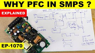
These drives require a front-end power PFC regulator to shape the input current of the power supply and
to meet the standards for power factor and current THD, such as IEC61000-2-3. A PFC circuit shapes the
input current of the power supply to be in phase with the mains voltage and helps to maximize the real
power drawn from the mains. The front-end PFC also offers several benefits:
• Reduces RMS input current
For instance, a power circuit with a 230-V/5-A rating is limited to about 575 W of available power with a
power factor (PF) of 0.5. Increasing the PF to 0.99 almost doubles the deliverable power to 1138 W,
allowing the operation of higher power loads.
• Facilitates power supply hold-up
The active PFC circuit maintains a fixed, intermediate DC bus voltage that is independent of the input
voltage so that the energy stored in the system does not decrease as the input voltage decreases. This
maintenance allows the use of smaller, cost effective bulk capacitors.
• Improves efficiency of downstream converters
The PFC reduces the dynamic voltage range applied to the downstream inverters and converters. As a
result, the voltage ratings of rectifiers can be reduced, resulting in lower forward drops. The operating
duty cycle can also be increased, resulting in lower current in the switches.
This reference design is a boost PF regulator implemented using the UCC28180 device as a PFC
controller for use in all appliances that demand a PF correction of up to 3.5 kW. The design provides a
ready platform of an active front-end to operate downstream inverters or DC/DC converters operating on a
hi-line AC voltage range from 190-V to 270-V AC.
This design demonstrates a high power density PF stage in a small form factor (215 × 145 mm) that
operates from 190-V to 270-V AC and delivers up to 3.5 kW of continuous power output to drive inverters
or converters at more than a 98% efficiency rate without an SiC device. This TI Design also provides
flexibility for the boost follower configuration, in which the boost voltage can be varied with AC input
voltage, but only can work on the boosted voltage when it is above the peak input voltage. The boost
follower configuration helps reduce switching losses in the PFC regulator and the downstream inverter or
converter. This design also gave an efficiency comparison in using MOSFET and IGBT, which can help
customer to choose efficiency or cost is preferred.
Above all, this TI Design meets the key challenges of appliances to provide safe and reliable power with
all protections built in while delivering a high performance with low power consumption and a very
competitive bill-of material (BOM) cost.
3500 watt pfc circuit,3.5 kw pfc circuit,power,power factor correction,power factor explained,Power Factor Correction Reference Design Circuit,pfc circuit,pfc circuit explained,power factor,UCC28180 PFC Controller,ucc28180,UCC27531D,Low-side driver,Low-Side Gate Driver,Calculating PFC Choke Inductor,Boost Follower Control Circuit,fix output pfc circuit,pfc boost converter,pfc boost converter design,haseeb electronics urdu,haseeb electronics,power supply


Информация по комментариям в разработке