✅ Join us here, get awesome perks, and support us, all at once:
/ upmation
Before you watch this video, we suggest watching the previous episodes or reading their blog posts here:
👉 How to Read Electrical Diagrams ▶ https://upmation.com/wiring-diagrams/
👉 How to Read PLC Wiring Diagram ▶ https://upmation.com/plc-wiring-diagram/
In this video, we will check out another real-world circuit diagram but this time from another perspective. I will show you the structure of a standard wiring diagram that belongs to a real-world customized machine.
As this whole lengthy document is associated with a singular packaging machine, the designer has integrated the wiring diagram along with several other sections in one single document.
Right after the cover sheet is the index of the wiring diagram that shows which page is allocated to what mechanism.
After the Index, there is a page including the wires' color code of the electrical panel. For instance, in this specific panel, you can find and track 110 VAC wires in red color and 220-volt AC in Grey color.
On this page, we can also find some general specifications of the electrical panel, control stations, junction boxes, and so on like their enclosure’s material, color code, Ingress protection rating, etc.
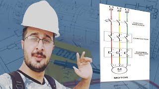
The first part of the electrical drawing is assigned to power distribution across the panel for different purposes. Whether it is a 3-phase power like here or it is a 1-phase or 24-volt control power.
Power distribution has happened until page 62. On the first page, the 3-phase power has been distributed inside the panel using a “Power Distribution Block.” It is nothing but some premade busbars with some screws on them for making the connections simple, easy, and safe.
Obviously, most of these three-phase feeders are going to supply our rotary consumers or electric motors.
In continue, we see the same configuration until we reach the single-phase power distribution used for some utility stuff like the panel lamps, sockets, fan, and the limit switch of the panel’s door.
The next part is assigned to the control circuit’s power supply which is 24 volts as we had explained in Episode 1.
As the designers have chosen the AS interface for some parts of the machine, the next page is about feeding the AS interface power supply with 3-phase power. From the output, different AS interface I/O modules and sensors have been supplied.
The next part is about exchanging some signals between different parts of the packaging machine.
After that, we reach wiring diagrams of the safety devices installed in different parts of the machine that are wired to the safety relays within the control panel.
The next part begins with some simplified schematics that give us a general overview of the control or automation network of this machine.
On the first page, you see the Siemens PLCs, Siemens ET200SP that acts as a remote I/O system, an AS interface master to control Distributed I/O network, the VFDs that are networked in daisy chain topology, a touch panel as the HMI or Human Machine Interface, and finally, an industrial Ethernet switch to connect all these together and to higher level PLCs.
This section illustrates the connection of the sensors, transmitters, and other instruments to the PLCs’ local Input and Output cards or Remote IO cards.
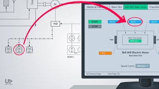
The next section that I am going to briefly review is the Variable Frequency Drives’ cabling and wiring diagram.
Next, is about the control stations or operator panels that are distributed all over the machine for different purposes.
We invite you to watch this video and see what the structure of an electrical wiring schematic is!
===========================
✅ Please SUBSCRIBE to get notified about the new videos: https://bit.ly/32mlhu9
===========================
Timestamps of this video:
00:00 Introduction
00:28 An overview of this Electrical Wiring Diagram
01:13 Coversheet, Index, Wires Color Code, etc.
02:54 Power Distribution
05:27 Signal Exchange Wiring, Safety Devices Wiring
06:43 Automation Network Configuration
08:04 Signals & Sensors Wiring, VFDs Wiring, Operator Stations Wiring Diagram
10:22 Electrical & Control Panel Internal Layout
10:43 Termination Diagram and I/O List
===========================
▶ If you've missed our most recent videos, watch them here:
Spool Valves: How They Work and How to Read Their Symbols
• Spool Valves: How They Work and How t...
Why Should You Use a Remote IO Panel (RIO Panel)?
• Remote I/O System for Industrial Auto...
What is a Directional Control Valve?
• Directional Control Valves (Hydraulic...
===========================
FOLLOW US on other Social Media
👉 INSTAGRAM ▶ / upmationdotcom
👉 TWITTER ▶ / upmation
👉 FACEBOOK ▶ / upmation
👉 LINKEDIN ▶ / upmation
===========================
#wiring #wiringdiagram #electricalwiring


Информация по комментариям в разработке