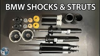
Part 1: Installing shocks and struts on a BMW 3 series 06 thru 12 (E90, E91, E92, E93)

Скачать Part 1: Installing shocks and struts on a BMW 3 series 06 thru 12 (E90, E91, E92, E93) бесплатно в качестве 4к (2к / 1080p)
У нас вы можете скачать бесплатно Part 1: Installing shocks and struts on a BMW 3 series 06 thru 12 (E90, E91, E92, E93) или посмотреть видео с ютуба в максимальном доступном качестве.
Для скачивания выберите вариант из формы ниже:
Cкачать музыку Part 1: Installing shocks and struts on a BMW 3 series 06 thru 12 (E90, E91, E92, E93) бесплатно в формате MP3:
Если иконки загрузки не отобразились, ПОЖАЛУЙСТА,
НАЖМИТЕ ЗДЕСЬ или обновите страницу
Если у вас возникли трудности с загрузкой, пожалуйста, свяжитесь с нами по контактам, указанным
в нижней части страницы.
Спасибо за использование сервиса video2dn.com


![[DIY] How To Change Your Front Suspension on a BMW 3 Series - Bilstein B12 PRO [E90, E91, E92, E93]](https://i.ytimg.com/vi/A9_3BGOiec8/mqdefault.jpg)


Информация по комментариям в разработке