Join the HVAC Game Skool Community: https://www.skool.com/thehvacgame/about
This video shows how to read HVAC wiring diagrams and relate them directly to what you see in the field — step by step, on a real rooftop unit.
If wiring diagrams feel confusing or disconnected from the actual equipment, this walkthrough will help you slow things down and make sense of them the way a service tech does on a real call.
In this video, I break down a rooftop unit wiring diagram and trace it from the control circuit all the way to the condenser fan motor, comparing the diagram to the physical components inside the unit.
What this video covers:
• How to navigate confusing HVAC wiring diagrams
• How to relate the diagram to the actual unit
• Identifying relays, contactors, and capacitors
• Tracing wiring when a non-OEM motor has been installed
• Using the diagram to determine whether a low-ambient kit is present
• How to backtrack incorrect field wiring and return the unit to OEM standard
This is exactly how wiring diagrams are used in real service work — not just to memorize symbols, but to figure out what’s been changed, what’s missing, and what the unit is supposed to look like electrically.
This video is aimed at new HVAC technicians who want to build confidence reading electrical diagrams and understanding how power and control circuits actually move through the equipment.
If this helps you on a service call, make sure to like, subscribe, and follow for more real-world HVAC training.
Happy HVACing
_ _ _ _ _ _ _ _ _ _ _ _ _ _ _ _ _ _ _ _ _ _ _ _
PS: If you want more information on wiring diagrams, read this:
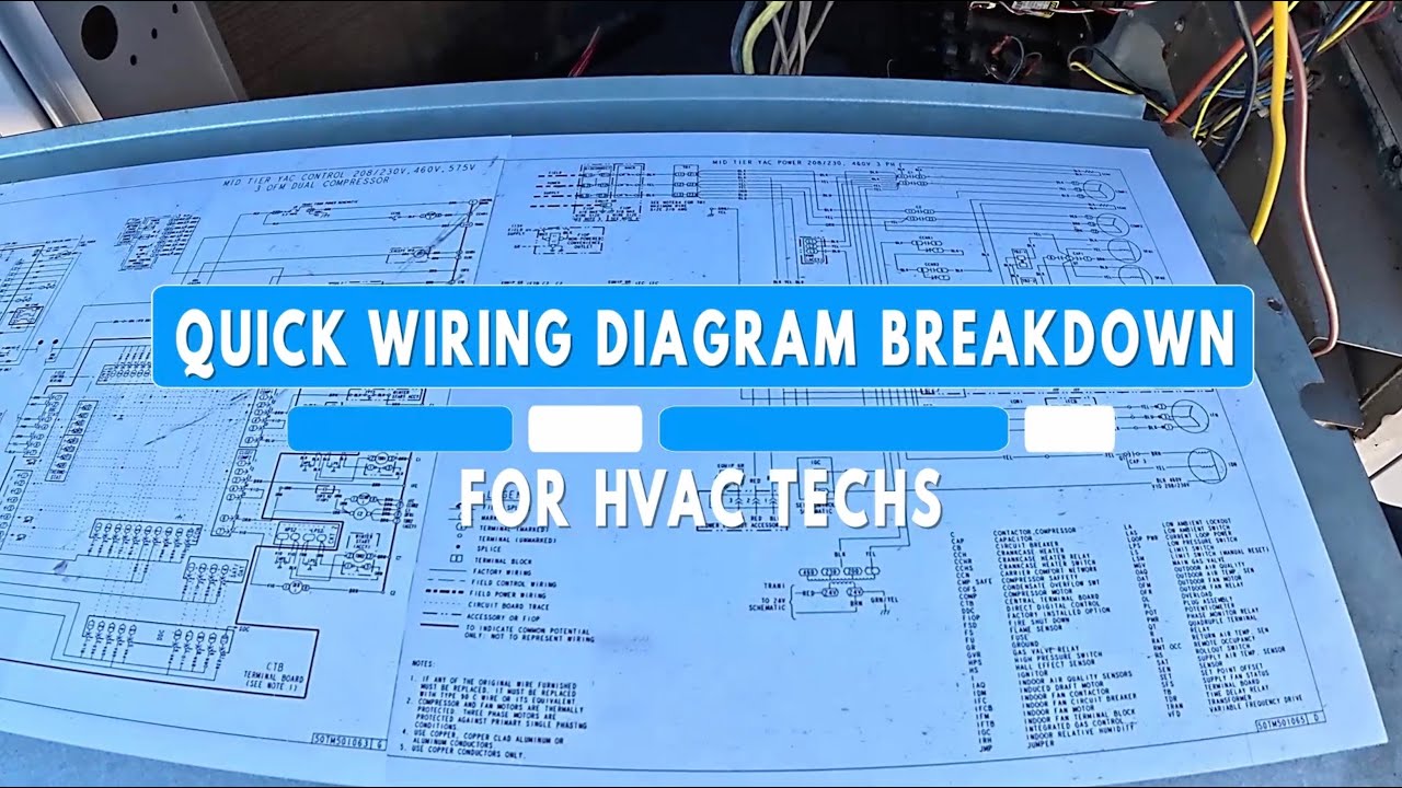
When you look at a wiring diagram, always start by zooming out and reviewing the legend and notes. This tells you how the diagram is meant to be read.
The legend also explains abbreviations used on the diagram. On many Carrier wiring diagrams, asterisks next to components indicate parts that may be factory-installed or optional field-installed components.
In most HVAC diagrams, solid lines represent factory-installed wiring inside the unit, while dashed lines show field-installed wiring that a technician is expected to connect. Power wiring is often drawn darker or bolder, and control wiring is usually lighter. Circular connection points represent component terminals, and splice symbols (similar to wire nuts) show where field connections are made.
There is an important difference between schematics (ladder diagrams) and connection diagrams. Schematics show how power flows between L1 and L2 and include a ground symbol (an inverted triangle). In a schematic, the contactor’s coil and contacts are drawn separately to show electrical function. Connection diagrams, on the other hand, show how components are physically arranged and wired inside the unit. Even though they look different, the component names and terminal numbers are the same across both diagrams.
Switch symbols can also tell you what type of device you’re looking at. Thermal switches use squiggly lines, pressure switches use a bell shape, and float switches use a circle. Normally closed switches appear closed on the diagram, and normally open switches appear open. Low-pressure switches have the line below the circle, while high-pressure switches have the line above it. An upside-down Y symbol indicates a time delay.
One common point of confusion is the letter C. On a compressor, C means the common point between the start and run windings. On a run capacitor, C is the shared terminal between the compressor and condenser fan motor. The letter is the same, but the function is different.
Finally, basic electrical symbols matter. A straight line followed by a curved line represents a capacitor. Spring-like symbols indicate inductive or magnetic windings, such as motors or coils. Jagged symbols represent resistive loads, which produce heat or light instead of magnetism.
#HVAC #WiringDiagrams #HVACTraining #NewHVACTech #RTU #HVACElectrical

Информация по комментариям в разработке