http://www.fiberoptics4sale.com/wordp...
http://www.fiberoptics4sale.com
Before the 1990s, data and voice cabling systems were proprietary, which means they were vendor-specific. Each vendor had its own cabling system design and it was hard to have products from different vendors to work together.
This no-standard approach had many problems as shown in the list.
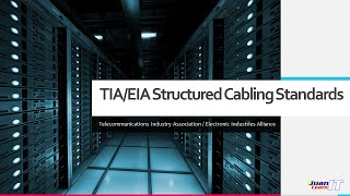
In the mid-1980s, the EIA was asked to develop a specification that would encourage structured, standardized cabling. In 1991, the TIA and EIA published the first version of the "Commercial Building Telecommunications Cabling Standard", better known as TIA/EIA-568.
So who are responsible for making these standard specifications?
A number of organizations around the world are devoted to the development of specifications that encourage interoperability. As long as the manufacturer follows the specifications, their devices should be able to work with other networking devices without any problem.
In the United States, there are the American National Standards Institute, or ANSI, the Electronic Industries Alliance, or EIA, and the Telecommunications Industry Association, or TIA.
The International Organization for Standardization, or ISO, is responsible for international standards around the world.
In the United States, we follow TIA/EIA-568-C as the structured cabling standard. This standard covers the following topics.
Subsystems of structured cabling. Such as horizontal cabling, backbone cabling, work area, telecommunication room, etc.
Cabling installation methods and practices.
Connector and pin assignments
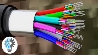
Cabling media types and performance specifications for horizontal and backbone cabling.
Connecting hardware performance specifications
Recommended cabling topology and distances
The definitions of cabling elements, such as horizontal cable, cross-connects, telecom outlets, etc.
The TIA/EIA-568C standard is actually composed of 4 documents.
The TIA-568-C.0 defines the generic telecommunications cabling for customer premises.
The TIA-568-C.1 defines the commercial building telecommunications cabling standard.
The TIA-568-C.2 defines balanced twisted-pair telecommunications cabling and components standard.
The TIA-568-C.3 defines optical fiber cabling components standard.
The ANSI/TIA-568-C.1 standard breaks structured cabling systems into six areas:
Horizontal Cabling
Backbone Cabling
Work Area
Telecommunication Rooms and Enclosures
Equipment Rooms
Entrance Facility (or Building Entrance)
I will briefly introduce each area in the following slides.
Horizontal cabling, as specified by ANSI/TIA-568-C.1, is the cabling that extends from horizontal cross-connect, intermediate cross-connect, or main cross-connect to the work area and terminates in telecommunications outlets.
Horizontal cabling includes the following:
Cable from the patch panel to the work area
Telecommunications outlets
Cable terminations
Cross-connections (where permitted)
A maximum of one transition point
Cross-connects in telecommunications rooms or enclosures
This figure shows a typical horizontal-cabling infrastructure in a star topology from a telecommunications room. The horizontal cabling is typically connected into patch panels and switches/hubs in telecommunications rooms.
Backbone cabling is also called vertical cabling, cross-connect cabling, riser cabling, or intercloset cabling.
Backbone cabling is necessary to connect entrance facilities, equipment rooms, and telecommunications rooms and enclosures. This figure shows backbone cabling that connects an equipment room with telecommunications rooms.
Backbone cabling consists of not only the cables that connect the telecommunications rooms, equipment rooms, and building entrances but also the cross-connect cables, mechanical terminations, or patch cords used for backbone-to-backbone cross-connection.
The work area is where the horizontal cable terminates at the wall outlet, also called the telecommunications outlet. In the work area, the users and telecommunications equipment connect to the structured-cabling infrastructure.
The work area begins at the telecommunications area and includes components such as:
Patch cables, modular cords, fiber jumpers, and adapter cables
Adapters such as baluns
Station equipment such as computers, telephones, fax machines, etc.
The telecommunications rooms and telecommunications enclosures are the location within a building where cabling components such as cross-connects and patch panels are located. These rooms or enclosures are where the horizontal structured cabling starts from.
So there you have it. Please leave your comment below if you'd like to see other topics.
Don't forget to visit fo4sale.com for more free fiber optic tutorials. I will see you in the next video!


Информация по комментариям в разработке