In this video, I discuss how to make your own UV Exposure Box. This is completely diy and very easy to make. The knowledge you could gain in this video is not only for PCBs but also for maybe creating a UV light cleanser for your phone or other objects This video will also help you in questions like LEDs computation, and how 555 timers work.
This project is powered by 12V DC power Supply, has its own timer and a safety measure. That when opened the UV LEDs won't emit anymore light.
Materials and Tools:
Electronics:
1. Power Supply (12V, 3A) and plug (1) {but you can use any supply, just change the resistor to have maximum output in the UV LEDs}
2. Reed switch (1)
3. Seesaw On-off switch (1)
4. Universal PCBs (at least 2 full 4x6 in size)
5. UV LED (https://shopee.ph/product/40370632/14...)
{specs of the LED (forward current : 20mA, forward voltage : 3.2 V to 3.4 V, dominant wavelength : 400 to 405 nm}
6. Resistors (90 ohms {12}, 6.2 k ohms {1}, 10 k ohms {2}, 20 k ohms {1}, 11.6 k ohms {1}, 24 k ohms {1}, 36 k ohms {1}, 47 k ohms {1}, 56 k ohms {1})
7. Solid Wires (2 meters)
8. 555 Timer {1}
9. LM741 Op amp {2}
10. Capacitor (4.7 mF {2})
Tools:
1. Drill/Cutter
2. Screw drivers
3. Bolts and Brass Holder
4.Digital Multimeter
5. Wire Stripper
6. Soldering Iron and Lead
7. Pliers
Case:
1. Shoebox
2. Magnet
There are two main parts in the project. First is the UV LED circuit, and the other one is 555 Timer Circuit. Both circuits are explained better in the website and in the next video.
Assembling the circuit is wiring all the buttons, and making sure the rotary has all their resistors.
The 555 Timer circuit is placed in a small PCB since it has few and little components
The UV LED circuit is the most troublesome circuit I made, because one wrong solder can malfunction the UV circuit. Also the PCB we used, was not the typical universal PCB Board. It already had connected lines. which was easier to use since you can map out the VCC and GND lines to the longer parts. but only downside is the supplies were so close, careful soldering is needed.
Testing the UV LED circuit, was a pain but somewhat a joy. As soon as you finished the soldering and everything is working. It feels REALLY REALLY GOOD. But after some tests using our 9V battery there were bad connections, and we had to check each solder. So do this incrementally, check each line before you solder the next line in the circuit. :)
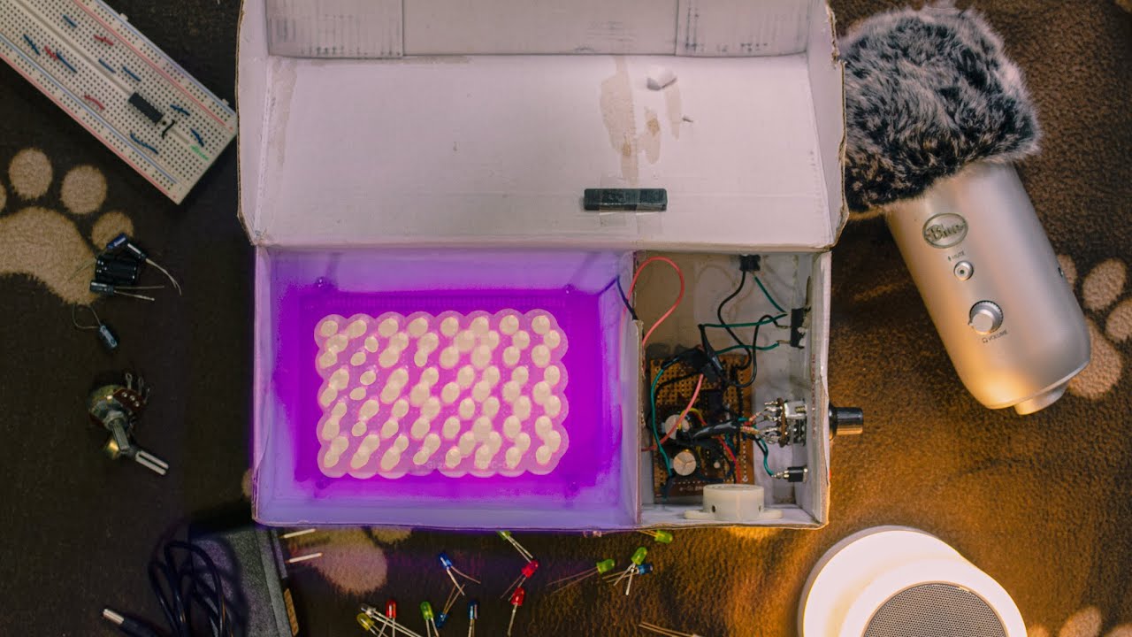
We used a shoebox for this project and the shoebox Gab had. already had a foldable lid. Soooo, we won't lose it. :) and we just cut the sides for the buttons, supply port, and switches. Made a divider for the UV LED and 555 Timer circuit. placed a reed sitch on top of the divider and a magnet on the lid, so that the UV LED will not turn ON when the shoebox is opened.
We tested. this project with some of our PCBs sadly only the 30 secs, had a good result. All the Timers were over exposed. What do you think we can improve? leave a comment and maybe we'll make an updated version of this.
Anyways, Give a Like if you liked the video. and go ahead and comment your questions or if you need help. Contact me and I'll be happy to help you.
I focus on 3d printing, electronics, and photography. I hope to upload more vids about my passions.
Timestamps
0:00 Intro
0:21 Why we did this
0:31 How It Works
0:49 Materials and Tools
1:01 Schematic Diagram
1:19 Assembling the Circuit
1:48 555 Timer Circuit
2:11 UV LED Circuit
2:58 Case Making
3:40 Testing
3:56 Outro
Contact me through:
Email: [email protected]
Instagram: @jnlreyes
Website: https://jnlreyes.myportfolio.com/uv-l...

Информация по комментариям в разработке