Due to a script error for voice over the dial indicator is called a "gage pin" in this video. It is clearly a dial indicator. This is corrected in our online content
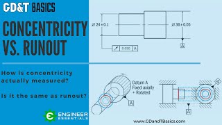
In circular runout a circular two-dimensional TZ is created around a datum axis. The arrow symbol for runout relates to the way it is measured, which should also help you understand how it works.
A part being measured for runout must be held by its datum axis and rotated. The controlled cross section can then have a dial indicator held against it. As the part rotates around its datum axis the dial indicator measures the total variation – or composite deviation – of the surface. If the composite deviation is small enough, then all parts of the surface fall into the prescribed circular TZ, which is a designated location from the axis.
This is different from circularity in that runout also controls in relation to a datum axis. So a surface that is incredibly round, but is off center from the referenced axis will not meet the callout.
Runout is also unique in that is can be used against any surface of the part as it rotates. This part can be held for rotation around it’s axis, and then surfaces that are parallel, angled, and perpendicular to the axis can have runout applied.
In each case the dial indicator would be held perpendicular to the surface feature and a two dimensional TZ would be created. Then as many cross sections as practical would be tested for their own two-dimensional TZ.
Note the orientation of the TZ changes with each surface, but the TZ is still a two dimensional circular band. However, due to orientation, and the part’s rotation, the perpendicular use of circular runout controls flatness instead if circularity, in a way.
Also note that for angled surfaces you must callout the basic angle so the dial indicator can be oriented perpendicular to the nominal surface.
Because of the measurement method used for runout, there are three options for parts that can practically be gauged for circular runout. These are ways in which the standards say you can define the required datum axis for circular and total runout controls. If your part does not meet one of these three descriptions you likely want to consider a different control.
The first application of circular runout is on parts with long diameters. A part with a long length vs diameter ratio makes is easy and effective to grab and rotate the part around the axis. The feature needs to be long enough to be able to stop the degrees of freedom physically, functionally, and consistently for effective inspection.
The second part type would be one with a short diameter and a plane. When the length vs diameter ratio is too small to consistently physically stop the desired degrees of freedom from the axis alone, a short axis can be paired with a plane.
For a part such as this, the plane may be your primary datum, and the axis is then held with an expanding chuck to allow functional and consistent rotation around the datum axis.
The third option would be parts with two (or more) short diameters “far” apart from each other. This definition is commonly met by cam shafts or similar rotating parts. The distance between the short diameter sections allow the part to be held and rotated around the datum axis.
Before we move on, let’s look at exactly what combination of other features are controlled by circular runout.
When this part is held and rotated for circular runout this inspection method also controls circularity for each cross section that is inspected.
This also controls flatness of individual rings perpendicular to an axis
As the held feature and considered feature are rotating around the same axis, a part that passes runout also controls the coaxiality of both features.
As all surface points fall within a circular TZ around a central axis, the median point of every diametrically opposed points also falls into a similarly narrow range, meaning that concentricity is also controlled.
Finally, as all cross sections are round and centered on the axis, circular runout automatically controls for Derived Median Line straightness as well.
The combination control of circular runout thus controls circularity, annular ring flatness, coaxiality of features, concentricity, and DML straightness.
You could control each of these separately, but why fill your drawing with several individual callouts that might cause as many individual inspection processes, when you can callout and inspect all of them with a combination control?
This callout is often used in applications where balance and high rpm are needed.


Информация по комментариям в разработке