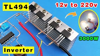
in this video i explained TL494 Pulse-Width-Modulation Control Circuits - Urdu / Hindi Language The TL494 in device incorporates all the functions required in the construction of a pulse-width modulation (PWM) control circuit on a single chip. Designed primarily for power-supply control, this device offers the flexibility to tailor the power-supply control circuitry to a specific application. The TL494 device contains two error amplifiers, an on-chip adjustable oscillator, a dead-time control (DTC) comparator, a pulse-steering control flip-flop, a 5-V, 5%-precision regulator, and output-control circuits. The error amplifiers exhibit a common-mode voltage range from –0.3 V to VCC – 2 V. The dead-time control comparator has a fixed offset that provides approximately 5% dead time. The on-chip oscillator can be bypassed by terminating RT to the reference output and providing a sawtooth input to CT, or it can drive the common circuits in synchronous multiple-rail power supplies. The uncommitted output transistors provide either common-emitter or emitter-follower output capability. The TL494 device provides for push-pull or single ended output operation, which can be selected through the output-control function. The architecture of this device prohibits the possibility of either output being pulsed twice during push-pull operation. The TL494C device is characterized for operation from 0°C to 70°C. The TL494I device is characterized for operation from –40°C to 85°C.
tl494 pwm circuit,tl494 power supply,tl494 inverter circuit,tl494 ic,pulse width modulation,pulse width modulation motor control,pwm controller,pwm controller ic,pwm controller ic for smps,pwm controller ic for inverter,tl494 working principle,tl494 ic working in hindi,tl494 tutorial,tl494 tutorial pdf,tl494 deadtime control,tl494 dc to dc converter circuit,tl94 calculator,tl494 circuit,tl494 circuit examples,tl494 circuit diagram,urdu,hindi,power supply


Информация по комментариям в разработке