For more videos on how wind tunnels work:
- Part 1: • How Wind tunnels Work – Contraction, ...
- Part 2: • How Wind tunnels Work – Blockage fact...
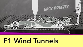
In this third video in our series "How Wind Tunnels Work" we look at wind tunnel measurement techniques - both some of the most widely used as well as some innovative ones.
Forces & moments
One of the most important output parameters of a wind tunnel test are the forces & moments on the object. To obtain these, the object is typically connected to a 3D force balance, which is a device that can measure the forces and moments around three perpendicular axes.
It's important to make sure that the influence of the connection part does not disturb the airflow too much, which is why they're often given an aerodynamic profile.
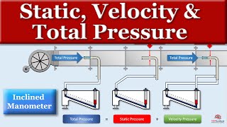
Surface pressure measurement
To measure the static pressure on the surface, you can use pressure taps. These are small holes drilled perpendicularly to the surface with a tube fitted to each hole in the model. These tubes are then sent to a pressure transducer which is typically located outside the wind tunnel, where the pressures are measured & logged.
If you want to measure the pressure on many locations on the surface of your object, you'll quickly end up with a huge set of cables that needs to be led outside. This is something you need to take into account during the design of your prototype.
Alternatively, you can work with miniaturized pressure transducers that fit within your model and then convert the measurements into digital data which is then sent to the outside world via a single cable to save space.
3D flow measurement
- Smoke: one of the oldest & most common techniques is to release smoke upstream of the object to trace the path of the air. This can lead to very insightful information in terms of where the separation point is located, what the size is of certain vortex structures and so on. But it's quite difficult to determine local flow velocities, so over the years, a number of alternatives have been developed.
- PIV - particle image velocimetry: tracer particles are released upstream of the area of interest. The size, density, ... of these particles are chosen in such a way that they follow the real flow nicely, without dropping to the ground or disturbing the flow pattern. They are then illuminated, typically in a 2D plane, using a laser. Then, they're filmed perpendicularly to that plane by high-speed cameras. By tracking & tracing the position of the individual particles between consecutive shots, one can reconstruct their path and calculate the velocity vector and flow field.
- 3D measurement probes: by measuring the differential pressures at the head of these multi-hole probes, you can obtain the static pressure and total pressure, the angle of attack and the velocity. If you then trace the position of the probe itself in 3D, you can reconstruct a 3D flow field.
-----------------------------------------------------------------------------------------------------------
The AirShaper videos cover the basics of aerodynamics (aerodynamic drag, drag & lift coefficients, boundary layer theory, flow separation, reynolds number...), simulation aspects (computational fluid dynamics, CFD meshing, ...) and aerodynamic testing (wind tunnel testing, flow visualization, ...).
We then use those basics to explain the aerodynamics of (race) cars (aerodynamic efficiency of electric vehicles, aerodynamic drag, downforce, aero maps, formula one aerodynamics, ...), drones and airplanes (propellers, airfoils, electric aviation, eVTOLS, ...), motorcycles (wind buffeting, motogp aerodynamics, ...) and more!
For more information, visit www.airshaper.com


Информация по комментариям в разработке